- Home
- >
- News
- >
- Industry News
- >
- High Voltage Diode Full Wave Rectifier
High Voltage Diode Full Wave Rectifier
High Voltage Diodes can be connected together to form a full wave rectifier that convert AC voltage into pulsating DC voltage for use in power supplies.
Full Wave Rectifier Circuit
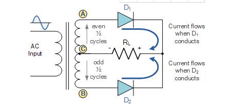
The full wave rectifier circuit consists of two high voltage diodes connected to a single load resistance (RL) with each diode taking it in turn to supply current to the load. When point A of the transformer is positive with respect to point C, diode D1 conducts in the forward direction as indicated by the arrows.
When point B is positive (in the negative half of the cycle) with respect to point C, diode D2 conducts in the forward direction and the current flowing through resistor R is in the same direction for both half-cycles. As the output voltage across the resistor R is the phasor sum of the two waveforms combined, this type of full wave rectifier circuit is also known as a “bi-phase” circuit.

